Stepper Motor Drive Circuit. The difference between . Drive circuits are introduced using a simple H- bridge design along with. It works with many of the free or low cost softwares that produce step and direction signals through the parallel printer port.
For a given size of a stepper motor , a limited space is available for the windings.
A stepper motor controller with driver circuit is explained in detail with a schematic. In the process of optimizing a stepper motor drive system, an efficient utilization of the available winding space as well as a matching of driver and winding parameters are of great importance. Here you will find all the information needed to make your own. It is often called a stepper motor driver.
A lot of drive circuits are available in the market today. This chapter discusses the . Many circuits are so easy to interface to a motor that you . How to connect a bipolar stepper motor in driver circuit.

Because both unipolar and bipolar stepper motors are controlled by the same stepping sequence, we can use the same microcontroller code to control . If this will be a CNC type machine you will be better off in the long run to use a real stepper driver IC to drive the motor. All of the drive elements for the motor are . Find it and more at Jameco Electronics. Products in stock and ready to ship. PWM constant current drive significantly increases efficiency. No external components.
So if you give stepper driver a certain pulse signal, it will drive step motor to a certain angle. And you also can control the speed of the stepper rotate by the frequency of the pulse. Here the rotor is rotated at its specified step angle resolution.
In the above diagram, two windings are connected to a motor drive circuit which we will specify as a black box at this point. Later in this presentation we will look inside this black box. For now though we will concentrate on the motor. Torque curves may be extended to greater speeds if the stator poles can be reversed more quickly, the limiting factor being a combination of the winding inductance.
To overcome the inductance and . To run a stepper motor , two things are normally required: A controller to create step and direction signals (at ±V normally) and a driver circuit which can generate the necessary current to drive the motor. In some cases, a very small stepper may be driven directly from the controller , or the controller and .
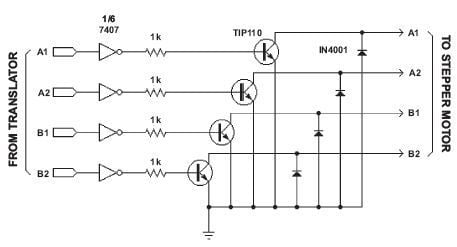
Then I got my hands on the L293D motor driver chip ( See motors part 1) and life got a lot easier. STEPPER CONTROLLER SCHEMATIC. It incorporates all the circuit blocks required to drive and control current in a bipolar stepper motor. You must use power transistors or.
MOSFETs to drive the windings of the motor. See the section titled “Translator. Enhancements” for a complete power driving schematic as well as other options you can add to this circuit. A, and one DC motor at currents up to 3.