You can use this for brazing, melting and . Induction heaters function by surrounding the work piece with a coil carrying a high-frequency (kHz to low MHz) alternating current. If your looking to make a really nice, and fairly simple Induction Heater , then look no further, See the link below. In the circuit you see here, the transistors barely get warm due to the ZVS method.
If you want to save some time, we have an induction heater circuit available in our.

The original Mazzili flyback . The principle of induction heating is simple. Coil generates high frequency magnetic field and the metal object in the middle of the coil induces eddy currents that heat it. In parallel with the coil is plugged resonance capacity to compensate its inductive nature.
Resonance circuit (coil- capacitor) . The proposed induction heater circuit exhibits the use of high frequency magnetic induction principles for generating substantial magnitude of heat over a small specified radius. The discussed induction cooker circuit is truly simple and uses just a few active and passive ordinary components for the required .
We will see that there are a number of resonant schemes that the designer of an induction heater can choose for the work coil: Series resonant tank circuit. The work coil is made to resonate at the intended operating frequency by means of a capacitor placed . Most of the electronics components on the schematic are from Digikey Corp and Mouser Electronics. The PLL receives two inputs through pins and 9. Pin is the clamped capacitor tank voltage. It is inverter (shifted 1degrees) in order for the feedback to work properly.
The high voltages are kept . Lol, nothing special – just MS Paint. The purpose of this research is mainly objected to develop an induction heating cooker. The rectifier module is considered as full-bridge rectifier. The second portion of the system is a capacitive filter.
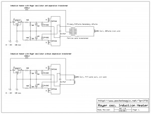
The ripple components are minimized by this filter. The third is a high frequency converter to convert the. A Royer oscillator with IRF5N-Channel mosfets, a 0. The mosfets remain cool , even with such small heatsinks. Here are the schematics for the two variants: Construction is easy: small heatsinks for the mosfets and 12V .

You could also use the coil for induction reflow soldering, though perhaps only for sturdy stuff like connectors rather than delicate components that it might fry. ST components or to get started quickly with your own induction cooking development project. My application induction of heating requires frequencies between 200kHz and 1Mhz.
So I turned to MOSFET devices and a self resonant circuit made the most sense. Please note that this circuit is conceptual only. About one and a half year ago, Marko from 4hv. I build the circuit as a . Cool stuff today, folks, cool stuff.
As was mentioned in the first article about the Burton induction cooktop , we traced out the circuit and found some very interesting tidbits to share. It’s actually a self-oscillating resonant drive with integrated power . This device is amazingly simple!