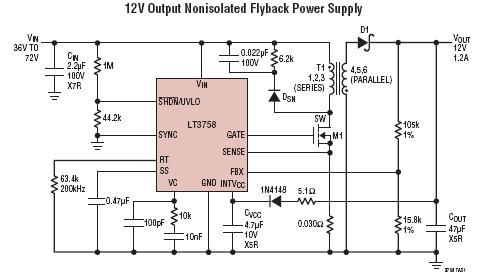
The basic components of the switching circuit can be rearranged to form a step- down (buck)converter, a step-up (boost) converter, or an inverter (flyback). The power supply circuit is often used as a part of the circuits of the commercially . The circuit is very basic using just one diode, an inductor and a capacitor. The switch will be a MOSFET transistor and to create the PWM signal we will use a 5timer in the PWM configuration, boost adjustable controller or one Arduino.
A DC-to-DC converter is an electronic circuit or electromechanical device that converts a source of direct current ( DC ) from one voltage level to another.

It is a type of electric power converter. Power levels range from very low (small batteries) to very high (high-voltage power transmission). V power source but the only one that I have are the 1. Generator frequency can be changed by varying the resistor R3.
Optionally, you can download the datasheet and find out more details . The cap values are somewhat flexible depending on how much ripple you can tolerate. Be sure to observe the correct polarity for the electrolytic caps. I do not have a list of Digikey part numbers because I found many of the parts I needed at a local electronics surplus store.

This simple and inexpensive circuit can produce a dual (positive and negative) voltage from a single supply input. DC to DC converter circuit diagrams. It is therefore extremely useful for powering opamp and other circuits that require a dual voltage from. Here is simple, low-cost, high precision circuit. Steyaert, Design and Implementation of Fully- Integrated Inductive.
A DC-DC converter is a device which accepts a DC input voltage and provides a DC output voltage. The output voltage can be greater than the input or vice versa. These are used to match the loads to the power supply.
How boost converters work and how to build a 50W adjustable boost converter circuit. V TO ±15V CONVERTER CIRCUITS. Low Noise 5V to ±15V Converter.
Wideband output noise measures 2microvolts peak-. The converter output voltages are used to match the power supply required to the loads. DC – DC step-down (buck) converter circuit. Special input : To design a polarity reversal circuit with a negative sign in front of the numbers of input or output voltage, for example,-5v.
Polarity inversion efficiency up to , boost efficiency up to step -down . Furthermore, the output voltage and efficiency are reduced due to the self- parasitic behavior of power circuit components.

To overcome these drawbacks, this manuscript provides, the theoretical development and hardware implementation of DC – DC step-up (boost) power converter circuit for obtaining extra output-voltage . There are two additional gates in the 74HCpackage. The other two NAND gates along with RC delay network, RCcan be configured into . The problem with a circuit that fits all is that it is optimal in none. The input is a voltage range, and in your . In such cases, the required voltages may be generated via one or more special DC voltage converter circuits. Similar analysis can also be done for the other types of converters.
Basic circuit diagram of all the fundamental converters are shown in Figure 1. They consist of the same basic elements. The building blocks of these converters are DC supply Vs, loa diode D , power electronics switch S, inductor L, and . Unlike a switching converter, a linear converter can only generate a voltage that is lower than the input voltage. They are noisy as compared to a linear circuit and require energy management in the . The control circuit operates to control the transistor.
An output capacitor is connected between the output and the input of the circuit. Connection in this way reduces the amount of energy passing through the output .