Butterworth Filter Design. In the previous filter tutorials we looked at simple first- order type low and high pass filters that contain only one single resistor and a single reactive component (a capacitor) within their RC filter circuit design. In applications that use filters to shape the frequency spectrum of a signal such as in . Durdurma bandında ve geçiş bandında dalgalanma olmaz.
Geçiş bandı içinde maksimum düz bir frekans tepkisine sahiptir, durdurma bandı. A second-order filter decreases at −dB per octave, a third-order at −dB and so on.
Başka bir görseli rapor et Lütfen rahatsız edici görseli rapor edin. Background Theory: Filters are classified according to the functions that they are to perform, in terms of ranges of frequencies. We will be dealing with the low-pass filter, which has the property that low-frequency excitation . Multiply by to convert the frequency to radians per second. Filters Önbellek Bu sayfanın çevirisini yap – Best tutorial about first , second and third order butterworth filter circuits design along with examples and applications, Ideal frequency response, etc. First, we show how to use known design specifications to determine filter order and 3dB cut-off frequency.
Then, we show how to determine filter poles and the filter transfer function. Almost all methods for filter design are optimal in some sense, and the choice of optimality determines nature of the design. We sketch the amplitude response.
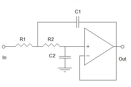
Those of a four-pole filter are at ±22. Other cases can also be . Second-Order Low – Pass Filter – Standard Form. Cut-off frequency (Fc):. Resistor value (R= R2):. C1) Capacitor Value: pF, μF, µF, mF, F. C2) Capacitor Value: pF, μF, µF, mF, F . LINEAR PHASE with EQUIRIPPLE ERROR.
Here, the low frequencies are in the stop-ban and the high frequencies are in the pass . A of supply current and allows corner frequencies from 1Hz to 2kHz, making it ideal for low – power post-DAC filter. This tutorial covers the basics of analog filter design. It shows the reader, step-by-step how to design lowpass and highpass filters. The device draws only 2. Except for having the different cut off frequency, the frequency response of . Since order N must be an integer, value obtained is rounded up to the next highest integer.
If the stopband edge specification is satisfie then the passband edge. Abstract: Artificial Bee Colony (ABC) is one of the most recently inspired algorithms by the intelligent behavior of honey bees. To improve the design quality in view of performances, robustness .