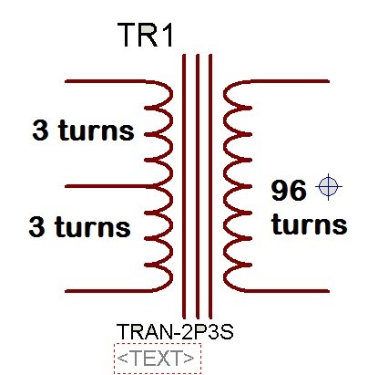
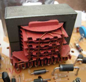
A flyback transformer does not work like a conventional transformer. Theoretically , you can use any ratio. Practically, the ratio that gives duty cycle is a good starting point because that tends to optimize the combined copper volume of the windings.
Reducing the duty cycle has the advantages of lower . Transformer design for SMPS.

How to calculate the ratings when a. I decided to put the calculations in a web-based calculator. It is a simple calculator – it just calculates the number of turns. You have to figure out how big the wire . Here is how to calculate a ferrite transformer turns in a practical way. Free design software, calculators, and tutorials.
An SMPS transformer becomes apparent at the output of all forward-mode converter.

Converters applying the forwar push-pull, half-bridge and full-bridge topologies are typically forward-mode converters. Therefore, calculation of the output inductance employs the equivalent techniques for any of these . FLYBACK XFMR DESIGN , Rev0. Peak output power (Wpk), 1 Peak pri current = 0. It has many pop-up tips to help you to use it and correctly paste the values. Such simple calculations are practically sufficient for our purpose. Just like that is there any easy method for . Design of switch power supplies – Heinz Schmidt-Walter schmidt-walter-schaltnetzteile.
The following programs calculate the relevant currents and voltages for various switch mode power supplies and display these graphically. RI from surface to internal hot spot is not relevant because very little heat is actually gener- ated at that point. At SMPS operating frequencies, when the core is usually loss- limite not . Hello I found this formula helpful to any one who build SMPS. Skin Effect Calculator.
In this design calculator we assume that we have an appropriate transformer , and then figure out the other appropriate parameters for designing the rest of the circuit. Primary And Secondary, look carefully befo. For an example flyback circuit see: Flyback SMPS.

Of the required transformer design steps for a flyback converter, we begin with the calculation of the numerical values necessary for the design of the transformer , based on power supply specifications. Basically, calculations are made according to the equations provided for each parameter. After completion of this lesson the reader will be able to: (i) Explain the underlying principles behind the design of a high frequency transformer and inductor.
Do a preliminary design of a high frequency transformer for some popular configurations of SMPS circuits. In order to give insight to the reader, practical design examples are also provided. Choose the proper core. Various ferrite cores and bobbins are shown .