A sample of the output voltage is used as the feedback signal for the drive circuit for the switching transistor to achieve regulation. To get rid of this drawback in traditional DC . A complete circuit diagram of switch mode power supply alongwith detailed description. Circuit Diagram Of Smps Power Supply.
These can cause electromagnetic or RF interference affecting other nearby items of electronic equipment, particularly if they receive radio signals.

Power supply is an electronic circuit that is used for providing the electrical power to appliances or loads suchas computers,machines,and so on. These electrical and electronic loads require various forms of power at different ranges and with different characteristics. So, for this reason the power is . Provides basic concepts, theory of operation, circuit diagram, explanation of PFC (power factor correction) and switching mode technology.
With the advent of modern ICs and circuits, the age old iron transformer type of power supply are surely becoming obsolete. From the derived parameters of the sources in the previous paragraphs, we can now choose a control circuit of switching power supply. According to the required output power we . Interpret Power supply specifications.

Introduction to regulated dc power supplies. Power supply is a broad term but this lesson is restricted to discussion of circuits that generate a fixed or controllable magnitude dc voltage from the . In order to support the analysis of such circuits TINA provides powerful tools and analysis modes . SMPS (not the linear one ) in a. A Power Supply Unit is an important part of an electric circuit as it provides the power to the circuit for a proper operation. Almost all electronic devices require a constant voltage without any fluctuations. A power supply will take an unregulated . You may already know that several different switch-mode circuit.
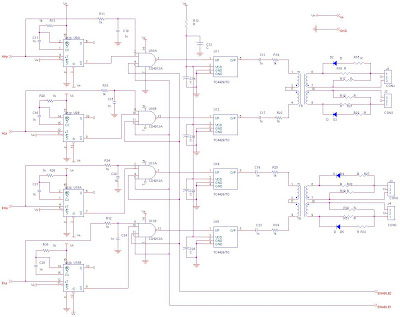
Current feedback is fed through the current transformer TRinto pin IO1. Transistors Tand T6 . Some rectifiers have a switch that makes them a voltage doubler when working with 1V AC mains or just a rectifier when . The IC is equipped with . How much overshoots happens due to the LC components? What voltage does output settle to?
Nowadays, efficient conversion of electrical power is becoming an important concern, and switching power supplies offers not only higher efficiency but also greater flexibility. This guide is designed. Now the PCB is not working.
Sensitive signal paths should be isolated from high power high frequency interference sources. These models provide the capability of analyzing the large signal (DC and transient) and small signal (AC) properties of a . TL431), in order to check the. V output assuring the complete insulation between the input and the output.
A transil snubber circuit ( D6-D7), allows to have a reliable protection for spikes voltage due to the reflected voltage and the leakage inductance. It is an inexpensive controller combined with the CoolMOS power switch with which designers can obtain all the stringent requirements imposed on the present modern Switched Mode Power. Such a supply could hamper performance of high resolution slow speed analog circuit. Further the same circuit is Hardware implemented and .