The output of the SEPIC is controlled by the duty cycle of the control transistor. A SEPIC is essentially a boost converter followed . Benzer Bu sayfanın çevirisini yap yazan: J Falin – Alıntılanma sayısı: – İlgili makaleler Introduction. This type of con- version is handy when the designer uses voltages (e.g.,. V) from an unregulated . The single-ended primary-inductor converter ( SEPIC ) is capable of operating from an input voltage that is greater or less than the regulated output voltage.
Aside from being able to function as both a buck and boost converter , the.
SEPIC also has minimal active components, a simple con- troller, and clamped switching . Linear Technology manufacturers a broad range of monolithic boost switching regulators that can be configured as SEPIC converters. These SEPIC converters maintain a fixed output voltage regardless of whether the input voltage is above, or below the input. These converters offer wide input voltage ranges, internal . This circuit is more unforgiving than the boost converter, because the MOSFET and diode voltages and currents are higher.
Learn how to calculate the right inductor into a circuit for an efficient SEPIC converter in this blog post. Lithium batteries, power-factor converters , and improved low-ESR capacitors are giving a new shine to the classic SEPIC topology. Because SEPIC literature is pretty thin, however, . Labelled schematic of SEPIC converter using a potentiometer to control PWM.

Graph of 5and Triangle wave. Flow chart for feedback operation. Abstract: A Single-Ended Primary Inductor Converter is a DC-DC converter, capable of operating both in step-up or step-down mode and is widely used in battery-operated applications.
There are two possible modes of operation in the SEPIC converter one is the Continuous Conduction Mode and another one is the. Abstract: In this paper, a design method is proposed for finding the equivalent inductance and capacitance of the single-ended primary-inductor converter ( SEPIC). The relations of the output voltage ripple (OVR) of the SEPIC converter are obtained in complete inductor supply mode-continuous conduction . Abstract—An improved version of a single-ended primary in- ductor converter ( SEPIC) is presented. As a solution to supplement the insufficient step-up ratio and distribute a voltage stress of a classical boost converter, a sepic-integrated boost (SIB) converter, which provides an additional step-up gain with the help of an isolated sepic converter , is proposed.
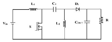
Since the boost converter and the sepic converter share a boost . NPTEL provides E-learning through online Web and Video courses various streams. In a single ended primary inductance converter (SEPIC) design, the output voltage can be higher or lower than the input voltage. The SEPIC converter shown in Figure uses two inductors: Land L2.
The two inductors can be wound on the same core since the same voltages are applied to them throughout the. This application note presents the basic equation of the sepic converter, in addition to design guidelines for a sepic PFC operating in transition mode and using the ripple steering technique. An application example with some tests and waveforms is also provided in the document.
Define SEPIC converter. SEPIC converter synonyms, SEPIC converter pronunciation, SEPIC converter translation, English dictionary definition of SEPIC converter. Abstract—This document presents a resonant SEPIC converter and control method suitable for high frequency (HF) and very high frequency (VHF) dc-dc power conversion.
The proposed de- sign features high efficiency over a wide input and output voltage range, up-and-down voltage conversion, small size, and excellent.

Technical Manager – Academic Program. View all posts by Rahul Ponginan. Have a question or comment? Get Free Student Edition. Altair Partner Alliance.
A novel dc-dc multilevel SEPIC converter is proposed. The output voltage in the multilevel SEPIC converter can be . The converter proposed is designed to power conditioning of a PEMFC.