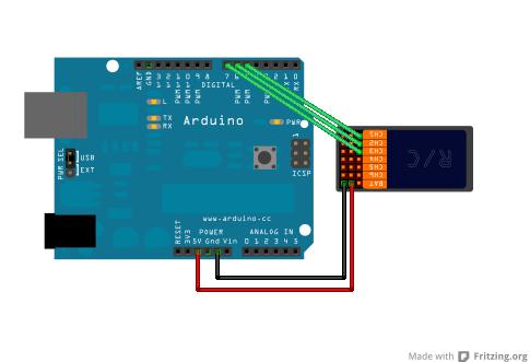
The Fading example demonstrates the use of analog output ( PWM ) to fade an LED. Pulse Width Modulation , or PWM , is a technique for getting analog with digital means. Digital control is used to create a square wave,.
Ken Shirriff with further editing by Paul Badger the original document. This article explains simple PWM techniques, as well as how to use the PWM registers directly for more control over the duty cycle and .

Writes an analog value ( PWM wave) to a pin. Can be used to light a LED at varying brightnesses or drive a motor at various speeds. After a call to analogWrite() , the pin will generate a steady square wave of the specified duty cycle until the next call to analogWrite() (or a call to digitalRead() or digitalWrite() ) on the same pin . With PWM you can do some pretty awesome things, in. In this tutorial, we will discuss about a new concept called PWM and how can this concept be used to control different devices like . One of the easiest ways to implement this is by using an Arduino.
We well take a look at some basic techniques for controlling DC motors and. We also use it here to control the brightness of each of the LEDs.

The diagram below shows the signal from one of the PWM pins on the Arduino. Since there are three different prescalers, the six PWM pins are broken up into three pairs, each pair having its own prescaler. Bu yazının başlığı elektronik açısından garip te gelse ifade ettiği şey bakımından gözümüzün önüne somut bir şey getirmektedir -bardağın yarısı dolu (yada boş). Bir büyüklüğü, potansiyeli, doluluğu elektronikte oluşturabilmek için PWM yöntemi geliştirilmiştir.
Eğer bardak tam dolu olsaydı 1dolu derdik, . There are a lot of tutorials online detailing the hardware PWM features of the arduino and how it relates to servo motor control. This instructable will show you how to use the hardware PWM to control a stepper motor instead. In this article learn PWM generation and control using arduino. Learn how to control DC motor speed using PWM and learn to control LED brightness. Arduino pins and are controlled by TCCR1B,.
Широтно-Импульсная модуляция, сокращенно ШИМ (англ. PWM ) Пример использования аналогового выхода (ШИМ) для управления светодиодом доступен из меню File-Sketchbook-Examples-Analog программы Arduino. Check out all the other tutorials in the series to learn more about Adruino. For example if you want a LED to be half bright, you . O conteúdo apresentado servirá de base . While setting up a ATMEGA controller for PWM signal is not easy, we have to define many registers and settings for a accurate signal, however in ARDUINO we don’t have to deal with all those things.
The PWM from UNO is quite easy. Analog pins actually make use of PWM to provide a any value of output voltage between – volts.

The number 0-2indicate the duty cycle of the pwm output we require. But you asked how to read. This is much harder since we have to talk about rising and falling edges. Includes schematics, descriptions and a sample sketch.
PWM ( Pulse-Width Modulation ) is a modulation technique that controls the width of the pulse based on modulator signal information. PWM can be used to encode information for transmission or to control of the power supplied to electrical devices such as motors.