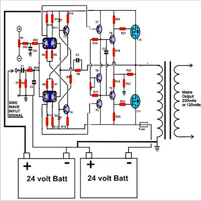
This application note describes the design principles and the circuit operation of the 800VA pure Sine. The pure Sine Wave inverter has various applications because of its key advantages such as operation with very low harmonic distortion and clean power like utility-supplied electricity, . Power inverter testing. The picture was taken in short-circuited.
NO it is not difficult to use microntollers, actually it could not be any easier than this.
For those wondering, Yes I myself designed the circuit concept, schematic and components but had to hire a programmer to write the . In this article I will discuss how to use push pull converter, sinusoidal pulse width modulation, h bridge and low pass LC filter to make pure sine wave inverter circuit diagram. I have already discuss all these topics in following articles. Pure sine wave inverters , on the other han produce a sine wave output identical to the power coming out of an. DC transmission as current flows from one end of a circuit to the other.
The post explains how an ordinary capacitive power supply may be transformed into a surge free voltage stabilized or variable voltage transformerless power supply applicable for almost all standard electronic loads and circuits. The idea was requested by Mr.
The Request Dear Swagatam, If you remember, . Solar Circuit Projects. Lock In Low Energy Rates. Simple Pure Sine Wave Inverter Circuit. They are power boar SPWM driver boar DC-DC driver board and protection board.
Worcester Polytechnic Institute Major Qualifying Project. Advisor: Professor Stephen J. Student Authors: Ian F. Modified Sine Wave Inverters. Appendix A: Circuit Schematic. Pure Sine wave inverter consist of a microcontroller unit which generates a switching signal of KHz, an H-bridge circuit to convert the signal into AC, a low pass LC filter circuit to block the high frequency components and the transformer unit to step-up the voltages.
Block diagram of sine wave circuit is . Basically the working waveform of the modified sine wave power inverter circuit presented here has been carved by positioning many discrete square waves in succession. This configuration is as good as a pure sine AC waveform and thus will be suitable to operate almost all appliances safely (my assumption). This video would be about finding the schematic used here, how to build a pure sine wave inverter , and a. What power do you expect?

There are other approaches too like using two alternating modlated SMPS, which is much more . Q Qforms the initial differential amplifier stage which appropriately raises the 1vpp sine signal at its .