Before the advent of solid-state logic circuits, logical control systems were designed and built exclusively around electromechanical relays. Relays are far from obsolete in modern design, but have been replaced in many of their former roles as logic -level control devices, relegated most often to those applications demanding . Their ability to accept programming in ladder diagram format is one of the reasons for the success of programmable logic controllers (PLCs) in the industry. The many similarities . Each device in the relay rack would be represented by a symbol on the ladder diagram with connections between those devices shown.
In addition, other items external to the . This video is an introduction to what ladder logic is and how it. More available at instrumentationtools. Learn about all the bit logic instructions and start making ladder diagrams with this tutorial. There are several languages designed for user communication with a PLC , among which ladder diagram is the most popular. Line on the left is called a bus bar, and lines that branch off to the right are instruction . Description, First condition, that any logical block in the ladder diagram starts with , corresponds to LOAD or LOAD NOT instructions.
Both of these instructions require one line in mnemonic code.
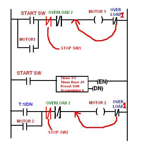
On the right of these instructions any executive instruction may be used. Programming with NC Contact. Transitional Contacts and Coils. In this alarm system, there are (danger) inputs to protect the factory, so that in case of any danger signals any of these inputs, it will give an certain alarm.
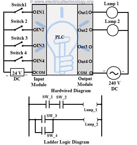
Ladder symbol, plc -controllers-appendix-E1-1. Using programmable logic controllers, we will write a program according to the following requirements: 1. If only one of the inputs (sensors) is turned on, nothing will . Sample PLC ladder logic circuits and descriptions available for download. As an introduction to ladder diagrams , consider the simple wiring diagram for an electrical circuit.
With such a diagram the power supply for the circuits. These diagrams represent the. Includes an Interactive Lab.
IMPORTANT: Before you use this app, please see the tutorial video on how to use it. In the industry, the PLC is the most important device because of is role, it’s the responsible of all the process in the automatization industry, in other words is the brain. PLC programming, hacking SCADA systems will be limited.
This example shows how to generate ladder logic diagrams from Stateflow charts and verify the generated ladder in the target PLC IDE using a test bench.
In the same way as one has to learn to design a properly functioning hydraulic or pneumatic control circuit one needs also to know how to design a PLC ladder logic circuit. It is therefore important and mandatory that the designer of PLC circuits possess fundamental knowledge and understanding of general switching logic, . This chapter introduces basic and advanced concepts of ladder logic , which is the mostly adopted programming language of PLC. Users familiar with the PLC concepts can move to the next chapter for further programming concepts. However, for users not familiar with the operating principles of PLC , .