It is a number by which the performance of an amplifier or a radio receiver can be specifie with lower values indicating better performance. Also, the IEEE Long Island section of IEEE MTT-S has some good lecture notes on noise that are worth checking out. The weakest signal a receiver can discriminate is a function of how much thermal noise the receiver adds to the signal.
Thermal noise is a random fluctuation in voltage caused by the random motion of charge carriers in any conducting medium at a temperature above . Purnachandar Poshala, Rushil KK, Robin Gupta.
This application report gives a method to calculate the effective noise figure of the whole signal chain and how knowing this helps correlate it with effective noise floor and dynamic range calculations . The three approaches are compared in a table. Modern receiving systems must often process very weak signals, but the noise added by the system components tends to obscure those very weak signals. Sensitivity, bit error ratio (BER) and noise figure are system parameters that characterize the ability to process low-level signals.
Of these parameters, noise figure. Read the key details about noise figure used for specifying the sensitivity performance of radio receivers and other components in radio communications systems. Of course, in addition to noise, the input to an amplifier in a receiver will typically include our desired signal.

Say the power of this input signal is in s. The output of the amplifier will therefore include both a signal with power . Commonly used figures-of-merit include noise figure (NF), sensitivity, minimum discernable signal (MDS), carrier-to-noise ratio (CNR), error vector magnitude (EVM), signal-to-noise ratio (SNR) and bit-error rate (BER). It is the decibel representation of the noise factor that determines the sensitivity of the amplifier is decreased to an incoming signal due to its internal noise. It is defined as the ratio of total output noise power to the output noise due to the input source.
Calculates the cascaded gain and noise figure for a system based on the values you enter for each stage. Receivers” as used here, is general in sense and the concepts are equally applicable to the individual components in the receiver cascade, both active and. Türkçe online sözlük Tureng. Kelime ve terimleri çevir ve farklı aksanlarda sesli dinleme. Noise Figure and Noise.
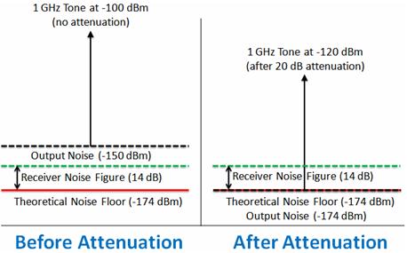
The noise figure is a measure of the excess noise added in an amplifier. Some amount of excess noise is unavoidable e. This application note describes in detail the steps required to make a noise figure measurement on a spectrum analyzer using the “Y Factor” technique. Background equations are presented for each step of the calculation.
In addition, guidelines are provided to ensure a repeatable measurement. This page on noise factor versus noise figure describes difference between noise factor and noise figure.
The useful links to difference between various terms are provided here. Note that log must be to base 10. When using calculators and spreadsheets make sure that base is selected. SNR(out) as high as we can.
Yes, we want the output SNR as high as possible, because that means the best chance of recovering the message signal accurately. Kumar A(1), Edelstein WA, Bottomley PA. Circular loops are the most. Looking for noise figure ? Find out information about noise figure.
Explanation of noise figure. As we shall see, the two can be equated. A spectrum analyzer is a receiver, and we shall examine noise figure on the basis of a sinusoidal input.