Normal Operating Current. Accelerometer disabled). Shown images are ilustrative only.
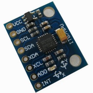
It is very accurate, as it contains 16-bits analog to digital conversion hardware . Photo: GY – 5breakout board.

This is a great IMU (Inertia Measurement Unit) for the price. Locate the blue GY – 5board in your kit, and the right-angle terminal strip supplied with it: GY – 5. It uses a standard I2C bus for data transmission. I²C çıkışı vermektedir.
Her eksende bitlik bir çözünürlükle çıkış verebilmektedir. Pinler arası boşluk standart olarak ayarlandığı için breadboard veya farklı devre . Ecco lo schema elettrico del modulo GY – 5per chi vuole costruirselo da solo: GY – 521. Ora passiamo al tutorial vero e proprio .
This sensor board has a voltage regulator. V to the VCC the resulting voltage (after the onboard voltage regulator) might be too low for a. Register names according to the datasheet. Took a while to get information and used to the readings, but very accurate and worth it after . Датчики определения положения в пространстве широко используются в мобильных устройствах, а для самоделок чаще всего применяются в квадрокоптерах.
Также, его можно применить . By combining a MEMS 3-axis gyroscope and a 3-axis accelerometer on the same silicon die t. Available schematic symbol, footprint and datasheet specification. Итак, вдохновимся сегодня тем, что всегда вдохновляло ведущих передачи Очумелые ручки и приступим. А задача у нас следующая.
Подключиться к датчику, 2. Получить какие-то данные 3. Придумать,что с этими данными делать. Купить GY – 5можно здесь 1. It is preferred to apply 5V to the VCC pin of the sensor board because by applying 3. V the resulting voltage (after the onboard voltage regulator) might be too low for a good working I2C bus. The board has pull-up resistors on the I2C-bus.