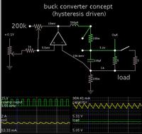
An error amplifier is most commonly encountered in feedback unidirectional voltage control circuits, where the sampled output voltage of the circuit under control, is fed back and compared to a stable reference voltage. Any difference between the two generates a compensating error voltage which tends to move the output . The finite input and feedback circuit impedances are denoted Zi and ZF, respectively. Schematic of a Buck Converter Power Train and Voltage Mode PWM Control Loop Structure.
Of the many possible ways to handle a feedback error signal in a control loop, the best decision is to use the integrate error – amplifier output of the dedicated control IC, not an external error signal: The latter gives rise to several problems not immediately obvious. Many design engineers use a feedback .
Hi, can some one provide me materials or links of what is an error amplifier and how to design an error amplifier. How is an error amplifier different than a differential amplifier. Analog Design Center Önbellek Bu sayfanın çevirisini yap – The popularity of voltage-mode control and its multiplicity of variants, pervasive in step-down (an to a lesser extent, step-up) power converters, has placed particularly significant burden on the voltage loop error amplifier (EA) as it provides the compensating gain contribution to mitigate the rapid falloff in . All regulating power supplies require some sort of closed-loop control to force the output to match the desired value. Error Amplifier Design and Applications. The intended use of the TL4is a closed loop SMPS controller.
On the other han you are re-purposing TL4as a PWM motor controller. You only want the PWM function . Where analog electronics implementation is concerne and error amplifier would typically be a difference amplifier, or a proper differential amplifier.

Output will be a voltage equal to the difference between set-point (reference) and parameter value fed back, multiplied by gain (if any). To see a video on this topic by the author, click here. Here is a short collection of power-supply error – amplifier pitfalls that you can . Introduction to Synchronous Buck Converter with Voltage-Mode Error-.
A buck converter with voltage-mode control and voltage-mode error amplifier can be stabilized with a proportional-integral (PI) type of compensator. However, to have high performance a more sophisticated compensation network is require. I intend on building a power supply at some point in the future, and was wondering specifically about the error amplifier. Примеры перевода, содержащие „ error amplifier “ – Русско-английский словарь и система поиска по миллионам русских переводов. Motor Drives with Flyback, SEPIC, and Ćuk Combination.
Absolute Maximum Ratings (TA = 25°C unless otherwise specified). Stresses exceeding the absolute maximum ratings may damage the device. The device may not function or be operable above the recommended operating conditions and stressing . The transitions between these two modes, main operating mode and the protective mode, must be automatic and as smooth as possible.
However, this can be corrected by added a Forced Equilibrium Adapter that enables . In the previous sections, a basic approach to transfer functions was explained as an answer to the question, What are transfer functions? Here, we consider the transfer functions of specific circuit blocks. We begin by considering transfer functions of amplifiers.
Abstract— Typical Low Dropout Voltage regulators (LDO), uses an error amplifier in a linear closed loop.
The main advantage of such linear regulators is the low standby current due to the absence of switching. In addition, a fully integrated linear regulator with no external components is very attractive for applications with .